

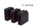
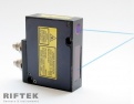
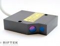


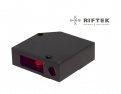






-
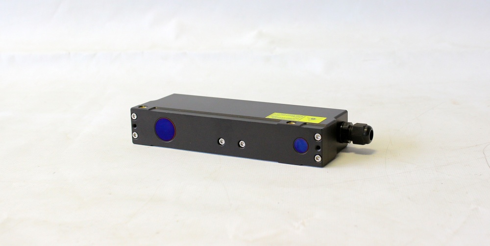
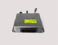
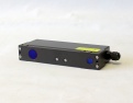
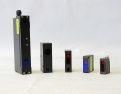
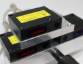
RF603 — universal sensors with 2 to 1250 mm operating ranges.
RF603HS — high speed sensors;
RF609, RF609Rt, RF609-Wi-Fi — laser probes;
RF600 — large-base and long range sensors;
RF605 — compact sensors. Not recommended for ordering, as it will soon be discontinued;
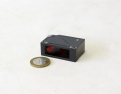
RF602 — super compact sensors;
RF60i — specialized laser sensors for pavement profile and texture measurement.

RF603 Series – Multi-purpose Laser Sensors
- Available with Red or Blue laser diodes;
- Varied diode powers for indoor or outdoor applications;
- Binocular sensors for laser scanning.


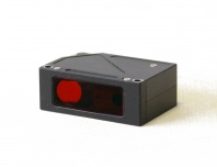
RF602 Series – Super Compact Laser Sensors
- Unique combination of dimensions, performance and operating ranges
- Available with RED and BLUE laser diods
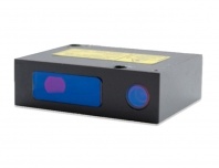
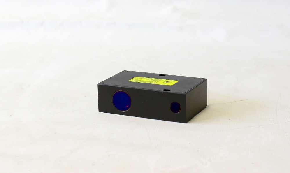
RF603HS Series – High Speed Triangulation Sensors
- Universal, high-speed laser sensor in compact case
- Available in Red and Blue diode wavelengths
- Ideal for capturing fast events and road profiling
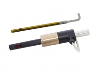
RF609 (RF609Rt) Series – Laser probes for holes inspection
- special sensors for holes geometry measurement

RF600 Series – Long-range/Large base Laser Sensors
- Up to 2.5 m measurement range
- Varied offset distances for custom applications
- Available in Blue diode wavelength for measuring hot objects
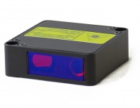
RF605 Series – Compact Laser Sensors
- sensors with excellent price/performance ratio

RF60i Series – Specialized Laser Sensors for Pavement Profile and Texture Measurement
- round laser spot of <1 mm diameter
- high resistance to solar radiation
- stable operation on wet surfaces
Laser Triangulation Sensors RF60х. Specification
| Parameter | Value | ||||||||||||||
|
Output Interface: |
|||||||||||||||
| digital |
RS232 (max. 460.8 kbit/s) or RS485 (max. 921.6 kbit/s) or RS232 and CAN V2.0B (max 1Mbit/s) or Ethernet and (RS32 or RS485) |
||||||||||||||
| analog | 4…20 mA (≤ 500 Ω load) or 0…10 V | ||||||||||||||
| Synchronization input | 2,4 – 5 V (CMOS, TTL) | ||||||||||||||
| Logic output | programmed functions, NPN: 100 mA max; 40 V max for output | ||||||||||||||
| Power supply, V | 9 …36 | ||||||||||||||
| Power consumption, W | 1,5..2 | ||||||||||||||
|
Environment resistance: |
|||||||||||||||
| Enclosure rating | IP67 ( for the sensors with cable connector only) | ||||||||||||||
| Vibration | 20g/10…1000Hz, 6 hours, for each of XYZ axes | ||||||||||||||
| Shock | 30 g / 6 ms | ||||||||||||||
| Operation temperature, °С |
-10…+60, (-30…+60 for the sensors with in-built heater), (-30…+120 for the sensors with in-built heater and air cooling housing) |
||||||||||||||
| Permissible ambient light, lx | >30000 | ||||||||||||||
| Relative humidity | 5-95% (no condensation) | ||||||||||||||
| Storage temperature, °С | -20…+70 | ||||||||||||||
| Housing material | aluminum | ||||||||||||||
Laser Triangulation Sensors RF603. Specification
(universal sensors with 2 to 1250 mm operating ranges)| RF603- | R-X/4 | X/2 | X/5 | X/10 | X/15 | X/25 | X/30 | X/50 | X/100 | X/250 | X/500 | X/750 | X/1000 | X/1250 | |
| Base distance X, mm | 39 | 15 | 15 | 15, 25, 60 | 15, 30, 65 | 25, 45, 80 | 35, 55, 95 | 45, 65, 105 | 60, 90, 140 | 80 | 125 | 145 | 245 | 260 | |
| Measurement range, mm | 4 | 2 | 5 | 10 | 15 | 25 | 30 | 50 | 100 | 250 | 500 | 750 | 1000 | 1250 | |
| Linearity, % | ±0.05 of the range | ±0.1 | |||||||||||||
| Resolution, % | 0.01 of the range (for the digital output only) | 0.02 | |||||||||||||
| Temperature drift | 0,02% of the range/°С | ||||||||||||||
| Max. measurement frequency, Hz | 9400 | ||||||||||||||
| Light source: |
red semiconductor laser, 660 nm wavelength or UV semiconductor laser 405/450 nm wavelength (BLUE version) |
||||||||||||||
| model | RF603 | ||||||||||||||
| output power | ≤0,2 | ≤5 mW | |||||||||||||
| laser safety Class | 1 | 3R (IEC60825-1) | |||||||||||||
| model | RF603L |
|
|||||||||||||
| output power | ≤0,95 mW |
|
|||||||||||||
| laser safety Class | 2 (IEC60825-1) |
|
|||||||||||||
| model | RF603Р | ||||||||||||||
| output power | ≤20 mW | ||||||||||||||
| laser safety Class | 3В (IEC60825-1) | ||||||||||||||
| Weight (without cable), gram | 100 | ||||||||||||||
Laser Triangulation Sensors RF603HS. Specification
(high speed sensors)| RF603HS- | X/2 | X/5 | X/10 | X/15 | X/25 | X/30 | X/50 | X/100 | X/250 | X/500 | X/750 | |||
| Base distance X, mm | 15 | 15 | 15, 25, 60 | 15, 30, 65 | 25, 45, 80 | 35, 55, 95 | 45, 65, 105 | 60, 90, 140 | 80 | 125 | 145 | |||
| Measurement range, mm | 2 | 5 | 10 | 15 | 25 | 30 | 50 | 100 | 250 | 500 | 750 | |||
| Max. measurement frequency, kHz | 70 | |||||||||||||
| Linearity, % | ±0.1 (70 kHz), of the range | |||||||||||||
| Resolution, % | 0.01 (70 kHz), of the range | |||||||||||||
| Temperature drift | 0,02% of the range/°С | |||||||||||||
| Light source |
red semiconductor laser, 660 nm wavelength or UV semiconductor laser 405/450 nm wavelength (BLUE version) |
|||||||||||||
| Output power | ≤4.8 mW | ≤20 mW | ≤80 mW | |||||||||||
| Laser safety Class | 3R (IEC/EN 60825-1:2014) | 3В (IEC/EN 60825-1:2014) | ||||||||||||
| Weight (without cable), gram | 110 | |||||||||||||
Laser Triangulation Sensors RF609 (RF609Rt). Specification
(special sensors for holes geometry measurement)| RF609 (RF609Rt)- | 9/19 | 16/48 | |||||
| Diameter of the laser sensor body, mm | 9 | 15 | |||||
| Range of controlled diameters, mm | 9.2...19 | 16...48 | |||||
| Depth of controlled holes, mm | on request | ||||||
| Base distance of the laser sensor, mm | 0.1 | 0.5 | |||||
| Working range of the laser sensor, mm | 5 | 16 | |||||
| Laser sensor linearity, % | ±0.05 of the range | ||||||
| Max. measurement frequency, Hz | 9400 | ||||||
| Light source | red semiconductor laser, 660 nm wavelength for both models; blue or UV semiconductor laser, 450 or 405 nm wavelength (BLUE version) only for 16/48 model | ||||||
| Output power, mW | ≤1 | ||||||
| Laser safety class | 2 (IEC60825-1) | ||||||
| Housing material | aluminum | ||||||
| Sync inputs (RF609), V | 2.4 – 24, trigger (IN input) | ||||||
| Sync inputs (RF609Rt), V | trigger (IN input), A-B encoder (IN and AL inputs) | ||||||
| Power supply, V | 9…36 | ||||||
| Power consumption, W | 1...1.5 | ||||||
| Weight (without cable), RF609, gram | 40 | 85 | |||||
| Weight (without cable), RF609Rt, gram | from 900 | ||||||
Laser Triangulation Sensors RF600. Specification
(large-base and long range sensors)| RF600- | X/10 | X/30 | X/40 | X/100 | X/250 | X/500 | X/600 | X/1000 | X/1000 | X/1500 | X/2000 | X/2500 | |
| Base distance X, mm | 230 | 300 | 330 | 500 | 230 | 300, 1000 | 230 | 380 | 1300 | 390 | 410 | 420 | |
| Measurement range, mm | 10 | 30 | 40 | 100 | 250 | 500 | 600 | 1000 | 1000 | 1500 | 2000 | 2500 | |
| Linearity, % | ±0.1 of the range | ||||||||||||
| Resolution, % | 0.01 of the range (for the digital output only) | 0.02 | |||||||||||
| Temperature drift | 0,02% of the range/°С | ||||||||||||
| Max. measurement frequency, Hz | 9400 or 70000 | ||||||||||||
| Light source |
red semiconductor laser, 660 nm wavelength or UV semiconductor laser 405/450 nm wavelength (BLUE version) |
||||||||||||
| output power | ≤4,8 mW | ≤20 mW | |||||||||||
| laser safety Class | 3R (IEC60825-1) | 3В (IEC60825-1) | |||||||||||
| Weight (without cable), gram | 500 | ||||||||||||
Laser Triangulation Sensors RF605. Specification
(inexpensive compact sensors)| RF605- | 25/50 | 45/100 | 65/250 | 105/500 | |
| Base distance X, mm | 25 | 45 | 65 | 105 | |
| Measurement range, mm | 50 | 100 | 250 | 500 | |
| Linearity, % | ±0.1 of the range | ||||
| Resolution, % | 0.02 of the range | ||||
| Temperature drift | 0,02% of the range/°С | ||||
| Max. sampling frequency, Hz | 2000 | ||||
| Light source | red semiconductor laser, 660 nm wavelength | ||||
| Output power, mW | ≤0,95 mW | ||||
| Laser safety Class | 2 (IEC60825-1) | ||||
| Weight (without cable), gram | 60 | ||||
Laser Triangulation Sensors RF602. Specification
(super compact sensors)| RF602- | 20/10 | 20/25 | 30/50 | 55/100 | 65/250 | 105/500 | |
| Base distance X, mm | 20 | 20 | 30 | 55 | 65 | 105 | |
| Measurement range, mm | 10 | 25 | 50 | 100 | 250 | 500 | |
| Linearity, % | ±0,05 of the range | ±0,1 | |||||
| Resolution, % | 0,01 of the range | 0,02 | |||||
| Temperature drift | 0,02% of the range/°С | ||||||
| Max. sampling frequency, Hz | 9400 | ||||||
| Light source |
red semiconductor laser, 660 nm wavelength or UV semiconductor laser 405 nm wavelength (BLUE version) |
||||||
| Output power, mW | ≤1 | ||||||
| Laser safety Class | 2 (IEC60825-1) | ||||||
| Weight (without cable), gram | 40 | ||||||
Laser Triangulation Sensors RF60i. Specification
(pavement measurement)| Model | RF603Р | RF603Р | RF607 | RF607 | RF607 | RF603Txt | |
| Base distance X, mm | 125 | 245 | 190 | 210 | 230 | 30 | |
| Measurement range, mm | 500 | 1000 | 500 | 200 | 250 | 30 | |
| Linearity, % of the range | ±0.05 | ±0.03 | ±0.05 | ||||
| Resolution, % of the range | 0,01 (for the digital output only) | ||||||
| Temperature drift | 0,02% of the range / °С | ||||||
| Max. measurement frequency, Hz | 9400 | 70000 | 9400 | ||||
| Light source | red semiconductor laser, 660 nm wavelength | ||||||
| Output power, mW | <20 | <80 | <1 | ||||
| Laser safety class (IEC/EN 60825-1:2014) | 3В | 2 | |||||
| Laser spot shape | elliptic | round | |||||
| Laser spot size "beginning-middle-end of the range", mm | 1,7х3- 0,16х0,2- 3х5 | 1,6х2,5- 0,5х0,8- 1,6х3,5 | 0,9-1-0,9 | 0,8-0,7-0,6 | 0,8-0,7-0,5 | 0,06-0,025-0,06 | |

- Thickness

- Object Dimensions

- Objects Sorting
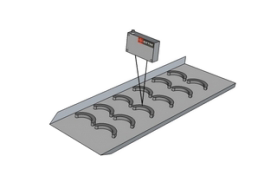
- Runout

- Profiling

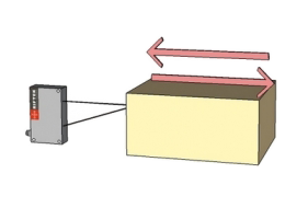
- Object/Target Displacements
Laser scanning of the inner surface of the tubes using RF609-9/19 triangulation sensor
Order information for Laser Triangulation Sensor RF603
RF603(BLUE)(L/Р).F-X/D(R)-SERIAL-ANALOG-IN-AL-СС(90X)(R)-M-H-P-B
| Symbol | Description |
| (BLUE) | Blue (405/450 nm) laser option |
| L/P | Laser safety class: L - Class 2, P - Class 3B |
| F | Max. measurement frequency, kHz (2 or 10) |
| X | Base distance (beginning of the range), mm |
| D | Measurement range, mm |
| (R) | Round shape laser spot (see p. 18.3) |
| SERIAL | The type of serial interface: 232 (RS232) or 485 (RS485); CAN or ET (Ethernet) |
| ANALOG | Attribute showing the presence of 4…20 mA ( I ) or 0…10 V ( U ) |
| IN | Trigger input (input of synchronization) presence |
| AL | User programmed input/output signal |
| CC(90X)(R) |
Cable gland - CG, or cable connector - CC (Binder 712, IP67) Note 1: sensors with CAN or Ethernet interfaces have 2 connectors or two cable glands. Note 2: 90(X) option – angle cable connector (see. p. 18.4.) Note 3: R option – robot cable |
| M | Cable length, m |
| H | Sensor with in-built heater |
| P | Sensor with protective air cooling housing (see p. 18.1.) |
| B | Sensor with spray guard (see p. 18.2) |
Example: RF603L.140/100R-232-I-IN-AL-24-СCR90A-3 – Class 2 laser, base distance – 140 mm, range – 100mm, round shape laser spot, RS232 serial port, 4…20 mA analog output, trigger input and AL input are available, cable connector, angle type, position "A", robot cable, 3 m cable length.
Order information for Laser Triangulation Sensor RF603HS
RF603HS(BLUE).F-X/D(R)-SERIAL-ANALOG-IN-AL-СС(R)(90)-M-H-P-B
| Symbol | Description |
| (BLUE) | Blue (405 nm) laser option |
| F | Maximal sampling frequency, 60 or 120 or 160 kHz. |
| X | Base distance (beginning of the range), mm |
| D | Measurement range, mm |
| (R) | Round shape laser spot (see p.18.3.) |
| SERIAL | The type of serial interface: (RS232 and Ethernet) – 232-ET or (RS485 and Ethernet) – 485- ET. |
| ANALOG | Attribute showing an analog output presence 0…10 V (U). |
| IN |
User programmed signal, which has several purposes:
1) Trigger input (input of synchronization). |
| AL |
User programmed signal, which has several purposes. It can be used as: 1) Logical output (indication of run-out beyond the range). 2) Line of mutual synchronization of two and more sensors. 3) Line of hardware zero setting. 4) Hardware laser switch ON/OFF. 5) Encoder_B input. 6) Status line input. 7) Input for Ethernet restart. |
| CC(90X)(R) |
Cable gland - CG, or cable connector - CC (Binder 712, IP67). Note 1: 90(X) option – angle cable connector (see. p. 18.4.). Note 2: R option – robot cable. |
| M | Cable length, m |
| H | Sensor with in-built heater |
| P | Sensor with protect air cooling housing (see p.18.1) |
| B | Sensor with spray guard (see p.18.2.) |
Example: RF603HS.60-140/100R-232-ET-U-IN-AL-24-СCR90A-3 – 60 kHz sampling frequency, base distance – 140 mm, range – 100 mm, round shape laser spot, RS232 and Ethernet serial port, 0…10 V analog output, trigger input and AL input are available, cable connector, angle type, position "A", robot cable, 3 m cable length.
Order information for Laser Triangulation Sensor RF609 and RF609Rt
RF609(Rt)(BLUE)-X/D-L-SERIAL-ANALOG--M
| Symbol | Description |
| Rt | Probe with a built-in slip ring. |
| (BLUE) | Blue laser option (405 nm or 450 nm). Only for 16/48 probes. |
| X | Minimum controlled diameter, mm. |
| D | Maximum controlled diameter (when the probe is located along the hole axis), mm. |
| L | Probe length (prior consultation with the manufacturer is required). |
| SERIAL | Type of serial interface for RF609Rt: 232 (RS232) or 485 (RS485) |
| ANALOG | Attribute showing the presence of analog output for RF609Rt: 4…20 mA (I) or 0…10 V (U). |
| M | Cable length, m. |
Example: RF609Rt-9/19-100-232-I-3 – Probe with a built-in slip ring, red semiconductor laser, range of controlled diameters - 9...19 mm, probe length - 100 mm, RS232 serial port, analog output 4…20 mA, cable length - 3 m.
Order information for Laser Triangulation Sensor RF600
RF600(BLUE).F-X/D(R)-SERIAL-ANALOG-IN-AL-СС(90X)(R)-M-H
| Symbol | Description |
| (BLUE) | Blue (405/450 nm) laser option |
| F | Max. measurement frequency, kHz (10 or 70) |
| X | Base distance (beginning of the range), mm |
| D | Measurement range, mm |
| (R) | Round shape laser spot |
| SERIAL | The type of serial interface: 232 (RS232) or 485 (RS485); CAN or ET (Ethernet) |
| ANALOG | Attribute showing the presence of 4…20 mA ( I ) or 0…10 V ( U ) |
| IN | Trigger input (input of synchronization) presence |
| AL | User programmed input/output signal |
| CC(90X)(R) |
Cable gland - CG, or cable connector - CC (Binder 712, IP67) Note 1: sensors with CAN or Ethernet interfaces have 2 connectors or two cable glands. Note 2: 90(X) option – angle cable connector Note 3: R option – robot cable |
| M | Cable length, m |
| H | Sensor with in-built heater |
Example: RF600.10-380/1000-232-I-IN-AL-ССR90А-3 – Sensor RF600, max. measurement frequency – 9.4 kHz, base distance – 380 mm, range – 1000 mm, RS232 serial port, 4…20 mA analog output, trigger input and AL input are available, cable connector, angle type, position "A", robot cable, 3 m cable length.
Order information for Laser Triangulation Sensor RF605
RF605-X/D-SERIAL-ANALOG-IN-AL- СС(R)-M
| Symbol | Description |
| X | Base distance (beginning of the range), mm |
| D | Measurement range, mm |
| SERIAL | Type of serial interface: RS232 - 232, or RS485 - 485 |
| ANALOG | Attribute showing the presence of 4…20 mA ( I ) or 0…10V ( U ) |
| IN | Trigger input (input of synchronization) presence |
| AL |
Programmed signal, which has triple purpose. It can be used as 1) logical output; 2) line of mutual synchronization of two and more sensors 3) line of hardware zero setting |
| CC(R) |
Cable gland - CG, or cable connector - CC (Binder 702, IP67) Note 1: R option – robot cable |
| M | Cable length, m |
Example: RF605-105/500-232-I-IN-СG-3 –base distance – 105 mm, range – 500 mm, RS232 serial port, 4…20mA analog output, trigger input is available, cable gland, 3 m cable length.
Order information for Laser Triangulation Sensor RF602
RF602(BLUE)-X/D-SERIAL-ANALOG-IN-AL--M
| Symbol | Description |
| X | Base distance (beginning of the range), mm |
| D | Measurement range, mm |
| SERIAL | The type of serial interface: 232 (RS232) or 485 (RS485) |
| ANALOG | Attribute showing the presence of analog output: 4…20 mA (I) or 0…10 V (U) |
| IN | Synchronization input |
| AL | User programmable input/output signal |
| (BLUE) | Blue laser option (405 nm or 450 nm) |
| M | Cable length, m |
Example: RF602-65/250-232-I-IN-AL-3 – red laser, base distance - 65 mm, measurement range - 250 mm, RS232 serial port, 4…20 mA analog output, synchronization input and AL output are available, cable length - 3 m.
Order information for Laser Triangulation Sensor RF60i
RF60i-X/D-SERIAL-ANALOG-IN-AL-СС(90X)(R)-M-H-P-B
| Symbol | Description |
| i | Index: 3Р or 7 or 3Txt |
| X | Base distance (beginning of the range), mm |
| D | Measurement range, mm |
| SERIAL |
The type of serial interface: (232 (RS232) or 485 (RS485)) and (ET (Ethernet)) |
| ANALOG | Attribute showing the presence of 4…20 mA ( I ) or 0…10 V ( U ) |
| IN | Sensor with trigger input (input of synchronization) |
| AL | User programmed input/output signal |
| CC(90X)(R) |
Cable gland - CG, or cable connector - CC (Binder 712, IP67) Note 1: sensors with the Ethernet interface have 2 connectors or two cable glands. Note 2: 90X option – angle cable connector (see. p. 18.3). Note 3: R option – robot cable |
| M | Cable length, m |
| H | Sensor with in-built heater |
| P | Sensor in protective housing with air cooling system (see p. 18.1.) |
| B | Sensor with spray guard (see p. 18.2) |
Example: RF603P-125/500-232-I-IN-AL-ССR90А-3 – Laser sensor for pavement profile and texture measurement RF603P, base distance - 125 mm, measurement range - 500 mm, RS232 serial port, 4…20 mA analog output, trigger input and AL input are available, cable connector, angle type, position "A", robot cable, 3 m cable length.
A laser triangulation sensor is a non-contact measurement device that determines the distance to an object's surface by analyzing the position of a reflected laser spot on an internal detector. The operating principle is straightforward: a semiconductor laser projects a focused spot onto the target surface. The reflected light is collected by a lens and directed onto a linear CCD array positioned at a known angle relative to the laser axis. As the distance to the object changes, the spot shifts along the array — and a signal processor calculates the exact distance from that shift.
The result is a precise, single-point distance or displacement value delivered in real time, without any mechanical contact with the surface. Riftek RF60x sensors provide this measurement with linearity down to ±0.05% of the range and sampling rates up to 70 kHz depending on the model.
Laser triangulation sensors are used wherever non-contact measurement of position, displacement, thickness, vibration, or surface profile is required — from precision machining environments to automated production lines and road surface inspection.
Both technologies use optical triangulation as their operating principle, but they solve fundamentally different measurement problems.
A laser triangulation sensor measures a single point. It returns one distance value per measurement cycle — the distance from the sensor to one spot on the object surface. This makes it the right tool for displacement, position, vibration, thickness, and level measurement, where you need fast, accurate data from a defined location.
A 2D laser scanner projects a full laser line rather than a point, simultaneously capturing hundreds or thousands of distance measurements across the object's cross-section. The output is a complete profile — shape, width, height, contour — rather than a single value. When the object or scanner moves, successive profiles combine into a 3D surface model.
The practical rule: if you need to know how far the surface is, use a laser triangulation sensor. If you need to know what shape the surface is, use a 2D laser scanner. For many production systems, both technologies are used together — triangulation sensors for fast point-based control, 2D scanners for geometry and profile verification.
The range of measurable parameters is broader than the name suggests. Riftek RF60x laser triangulation sensors are used for:
- Displacement and position — tracking the movement or position of a target relative to a fixed reference
- Dimensions — measuring the length, height, step, or thickness of components, including thin sheets and films
- Surface profile — building a 1D profile of a surface by scanning the sensor or moving the object
- Runout and vibration — detecting radial or axial runout of rotating parts, measuring vibration amplitude and frequency
- Sorting — detecting the presence, height, or position of objects on a conveyor for automated sorting
- Liquid and bulk material levels — non-contact level measurement in tanks, hoppers, and open containers
- Deformation — monitoring structural deflection or thermal expansion under load
The RF609 laser probe series extends this to inner diameter measurement of holes from 9 mm, making triangulation technology applicable to bore inspection tasks that standard external sensors cannot reach.
The RF60x line covers an exceptionally wide range — from 2 mm to 2,500 mm — distributed across specialized model series:
RF603 — the universal series. 26 models covering ranges from 2 mm to 1,250 mm. Linearity ±0.05% of range, sampling rate 9.4 kHz. Available with red or blue laser. The standard choice for most industrial measurement applications.
RF603HS — high-speed version of RF603. Same measurement ranges (2 mm to 1,250 mm) but with sampling rates up to 160 kHz. Designed for capturing fast events, vibration, and high-speed production processes.
RF602 — super compact sensors (39.5 × 30.5 × 17 mm, 40 g) for ranges from 10 mm to 500 mm. Linearity ±0.05%, sampling rate 9.4 kHz. Used where installation space is the primary constraint.
RF600 — large-base, long-range sensors covering 10 mm to 2,500 mm. Sensor body 170 × 61 × 31 mm, 500 g. Designed for remote measurement of large objects, hot surfaces, and outdoor applications.
RF609 / RF609Rt — laser probes for inner diameter measurement. Sensor body diameter from 9 mm, measuring holes from 9.2 mm to 48 mm in diameter. Accuracy ±2 µm.
RF60i — specialized sensors for pavement profile and road surface texture measurement. High solar radiation resistance, stable operation on wet surfaces, measurement frequency up to 70,000 Hz.
RF605 — compact sensors for ranges 50 mm to 500 mm. No longer recommended for new projects as this series is being phased out.
RF603 and RF603HS share the same housing, weight, and measurement ranges — from 2 mm to 1,250 mm — and are visually nearly identical. The key difference is sampling rate and the corresponding linearity specification.
RF603 measures at up to 9.4 kHz with linearity of ±0.05% of range. This is sufficient for the vast majority of industrial measurement tasks — dimensional control, displacement monitoring, level measurement, and profile scanning at standard production speeds.
RF603HS measures at up to 70 kHz — roughly 8 times faster — with linearity of ±0.1% of range at maximum speed. This makes it the right choice when the measurement target moves fast, vibrates, or when the event being captured is brief: high-speed extrusion lines, vibration analysis, road surface profiling from a moving vehicle, or any application where 9.4 kHz is insufficient to capture the dynamics of the process.
The trade-off is linearity: RF603HS at 70 kHz is rated at ±0.1% vs. ±0.05% for RF603. If your application does not require high speed, RF603 delivers better accuracy at lower cost.
The RF609 is a specialized laser probe designed for a task that standard external triangulation sensors cannot perform: measuring the inner diameter and geometry of holes, bores, and tubes from inside.
The probe body is cylindrical — 9 mm or 15 mm in diameter depending on the model — allowing it to be inserted into holes and measure the inner surface by rotating around the bore axis. It covers inner diameters from 9.2 mm to 48 mm with measurement accuracy of ±2 µm and a sampling rate of 9.4 kHz.
The RF609Rt variant includes a built-in slip ring, which allows continuous 360° rotation without cable winding — essential for fully automated inner diameter inspection integrated into production lines or CNC machines.
Use the RF609 when you need non-contact measurement of bore diameter, ovality, or inner surface profile — in applications such as precision machined holes, hydraulic cylinder bores, injector bodies, or any cylindrical cavity where an external sensor has no line of sight to the surface being measured.
Most RF60x sensors are available in both red (660 nm) and blue (405/450 nm) laser versions. The choice depends on the material and surface conditions of the measurement target.
Red laser (660 nm) is the standard option and performs well on the majority of industrial materials: metals, plastics, ceramics, painted surfaces, and machined parts. It is the right default choice unless the material presents a specific challenge.
Blue laser (405/450 nm) is recommended in three situations. First, for organic and semi-transparent materials — rubber, wood, food products, biological tissue — where a red laser penetrates below the surface and returns a diffuse, unstable signal. The shorter blue wavelength reflects cleanly from the surface layer without subsurface scattering. Second, for red-hot or incandescent metal surfaces, where the thermal emission spectrum overlaps with the red laser wavelength and degrades the signal-to-noise ratio; blue laser is far enough from the emission peak to remain stable. Third, for some translucent plastics and coatings where surface reflection with red laser is insufficient.
If your application involves any of these conditions, specify the BLUE option when ordering. For standard metallic and opaque surfaces in a factory environment, the red laser version is sufficient and typically more cost-effective.
RF60x sensors provide both digital and analog outputs, making them compatible with a wide range of industrial control systems and data acquisition equipment.
Digital interfaces:
- RS232 (up to 460.8 kbit/s)
- RS485 (up to 921.6 kbit/s)
- CAN V2.0B (up to 1 Mbit/s)
- Ethernet i
Analog outputs:
- 4–20 mA (load ≤ 500 Ω)
- 0–10 V
Additional I/O:
- Synchronization (trigger) input — CMOS/TTL, 2.4–5 V
- Programmable logic output — NPN, 100 mA max, 40 V max — configurable for range alarm, zero setting, mutual synchronization of multiple sensors, or hardware laser on/off control
For PLC integration, the analog output is the simplest path. For higher data rates or networked configurations, Ethernet and RS485 are the preferred options. The CAN interface is available for applications in automotive test environments or embedded systems where CAN buses are standard.
Interface type is specified at the time of ordering and is part of the model code.
Yes. The RF60x series is designed for industrial-grade operation, including demanding outdoor and high-contamination environments.
Standard environmental ratings across the series:
- Enclosure protection: IP67 (dust-tight, protected against temporary immersion) for sensors with cable connector
- Vibration resistance: 20 g / 10–1,000 Hz, tested for 6 hours on each of three axes
- Shock resistance: 30 g / 6 ms
- Operating temperature: -10°C to +60°C standard; -30°C to +60°C with built-in heater option; -30°C to +120°C with heater and air cooling housing
- Ambient light rejection: up to 30,000 lux — sufficient for most indoor and shaded outdoor conditions
- Housing material: aluminum
For outdoor applications with direct solar exposure — such as road surface profiling — the RF60i series is specifically engineered with high resistance to solar radiation and stable operation on wet or reflective surfaces. RF60i sensors have been tested for operation from moving vehicles at speeds requiring measurement frequencies up to 70,000 Hz.
For foundry and high-temperature environments, the air cooling housing option (suffix P in the model code) allows operation near hot objects and in elevated ambient temperatures without sensor damage.
The RF60i is a specialized sub-series within the RF60x family, developed specifically for pavement profile measurement, road surface texture analysis, and similar outdoor applications where standard sensors are limited by solar interference and surface conditions.
Key differences from the standard RF603:
Solar radiation resistance. RF60i sensors are designed to operate in direct sunlight without signal degradation — a condition that would compromise standard industrial sensors not optimized for high ambient light levels.
Laser spot geometry. RF60i models include variants with a round laser spot smaller than 1 mm in diameter, optimized for texture measurement where spot shape directly affects the spatial resolution of surface detail captured.
Measurement frequency. RF607 models within the RF60i series operate at up to 70,000 Hz — essential for road profiling from a moving vehicle, where the sensor must capture thousands of surface points per second to resolve texture and rutting at highway speeds.
Wet surface stability. RF60i sensors maintain stable operation on wet asphalt and concrete, where specular reflections from water films degrade the signal in standard sensors.
The RF60i series includes three model types: RF603P and RF607 for profile measurement across ranges up to 1,000 mm, and RF603Txt for high-resolution texture measurement with a 30 mm range and spot size down to 25 µm at mid-range.
Selection comes down to four parameters: measurement range, required accuracy and speed, physical installation constraints, and surface conditions.
Measurement range determines the base model series. For ranges up to 500 mm in a compact form factor, RF602 is the space-efficient choice. For ranges up to 1,250 mm with standard accuracy, RF603 is the universal option. For ranges beyond 1,250 mm — up to 2,500 mm — RF600 is the only option in the series.
Speed requirements determine whether RF603 (up to 9.4 kHz) is sufficient or whether RF603HS (up to 70 kHz) is needed. If your process moves faster than a standard sensor can track — high-speed extrusion, vibration measurement, fast sorting — RF603HS is the correct choice despite its slightly lower linearity at maximum speed.
Installation space matters when mounting locations are constrained. RF602 at 39.5 × 30.5 × 17 mm and 40 g is the most compact option in the series. For inner bore measurement, RF609 probes from 9 mm body diameter are the only applicable solution.
Surface and environment determine laser wavelength (red vs. blue) and whether protective options — built-in heater, air cooling housing, spray guard — are needed. For outdoor or road applications, RF60i is the specialized choice.
If your application falls outside standard parameters — unusual geometry, extreme temperature, specialized integration requirements — Riftek engineers configure sensors to task-specific specifications. Contact our technical team with your measurement range, target material, required accuracy, and installation constraints to identify the optimal configuration.