

The measuring machine is designed for non-contact measurement of geometrical parameters of objects, specifically suspension arms, and is a standalone software/hardware system.
Technical characteristics of the machine can be changed for a specific task.

3D Laser Measurement Machine RF1010SL

3D Laser Measurement Machine RF1010SL
| Parameter | Value | |
| Scanning range Y-axis, mm | 370 | |
| Scanning range, Z-axis, mm | 135 | |
| Scanning range Х (start of measurement, Z-axis), mm | 45 | |
| Scanning range Х (end of mesurement Z-axis), mm | 70 | |
| Measurement accuracy, X,Z axises, um | ±50 | |
| Measurement accuracy, Y axis, um | ±20 | |
| Sampling rate, profiles/s | 250 | |
| Speed, mm/s | up to 80 | |
| Parameters under control | see point 10.1.2. in manual | |
| Dimension, mm | 730х415х180 | |
| Weight, kg | 40 | |
| Power supply |
alternating-current mains with sampling rate (50 ± 1) Hz, |
|
| Power consumption, W | 300 | |
| Environment conditions | Environment temperature: +1..+350 С Relative humidity 25-65% | |
The work of the machine is based on the principle of 3D laser scanning of object/ objects with subsequent construction of a 3D computer model and determination of geometrical parameters from the model.
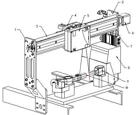
The machine structural design is illustrated in Figure 1 (machine with cover removed).
The machine comprises two columns 1,2, closed with the guide 3. The carriage 4, carrying the laser scanner 5, is mounted on the guide 3. Mounted on the column 1 the stepping motor 6 is connected to the ball screw (not shown) that drives the carriage 4. In the extreme positions of the carriage 4 limit switches (not shown) are mounted. There are a signal block 7 and a power supply 8 on the column
2. Laser scanner 5 radiation is formed in a line and is projected onto the controlled object 9. The resulting image of the contour (cross-sectional profile) 10 of the object is analyzed by a signal processor of the scanner which calculates the distance to the object (Z coordinate of points) for each of a plurality of points along the laser line on the object (X coordinate of points).
The machine operates as follows. The laser scanner mounted on the carriage moves along the object, the direction of the movement being the coordinate Y. The laser scanner determines the coordinates of the object profile points (X, Z) at fixed regular linear intervals along the Y coordinate defined by the stepper motor drive, fig. 2.

The result is a 3D computer model of the object in the form of Point Cloud with established profile coordinates (X,Y,Z). The required geometrical parameters are calculated from the resulting object model.
3D Laser Measurement Machine RF1010SL