


The inner surface of the large objects is subject to wear during operation. To prevent accidents, periodic monitoring of the degree of wear is necessary. Until now, this kind of control is carried out with manual measuring instruments, but such measurements are very time-consuming, not technologically advanced and do not provide the required amount of reliable information.
An automated laser system is designed for obtaining a complete 3D model of the inner surface large objects and wear calculation with high resolution and accuracy.
RF096-440/1440-2000 Series


Large objects inner surface inspection machine. Specification
| Parameter | Value | |
| Inner diameter measurement range, mm | 440...1440 | |
| Inner diameter measurement error, mm | ±0.5 | |
| Пространственное разрешение, точек/оборот | 2008 | |
| Scanning depth range, mm |
0...2000 (programmable parameter) |
|
| Минимальное расстояние между измеряемыми сечениями, мм |
1 (programmable parameter) |
|
| Linear displacement error, mm | ±0.1 | |
| Maximum sampling frequency, Hz | 9400 | |
| Light source |
red semiconductor laser, 660 nm wavelength |
|
| Output power, mW | <1 | |
| Laser safety class | 2 (IEC60825-1) | |
| Interface | Wi-Fi | |
| Power supply, V | Batteries 12V | |
| Weight, kg | 77 | |
Main functions of the software
The software is intended for:
- parameterization of the system and control of the scanning process,
- system calibration,
- formation of a 3D model of an object based on the data obtained during scanning,
- viewing a 3D model,
- comparison of models obtained at different points in time,
- comparison of the obtained model with the reference,
- calculation of shape deviation values (surface wear) of selected models,
- calculation of the circle parameters in any cross section of the object, namely the diameter (average, maximum, minimum), ovality, roundness,
- saving, reading and exporting data.
The operation of the machine is based on the principle of scanning the inner surface of the product by a rotating triangulation laser sensor.
The main components of the machine are shown in the figure, where 1 - installation frame, 2 - guide, 3 - centralizer, 4 - laser scanning module, 5 - burner surface; the tablet is not shown.

The frame (1) is attached to the end of the burner (5). The guide (2) is located along the axis of the burner and rests on the frame (1) on one side and on the centralizer (3) on the other. The centralizer is installed on the conical surface of the burner. The laser scanning module (4) is installed on the guide (2).
The machine operates as follows.
On command from the tablet, the laser sensor starts to rotate and the scanning module (4) moves along the guide (2). The laser sensor measures the distance to the burner surface. The polar coordinates of the burner surface points (distance to the surface measured by the laser sensor and the sensor rotation angle measured by the built-in encoder), synchronized with the linear position of the module, are transmitted to the computer. The program builds a 3D model of the inner surface, according to which the required geometric parameters and the wear are calculated.
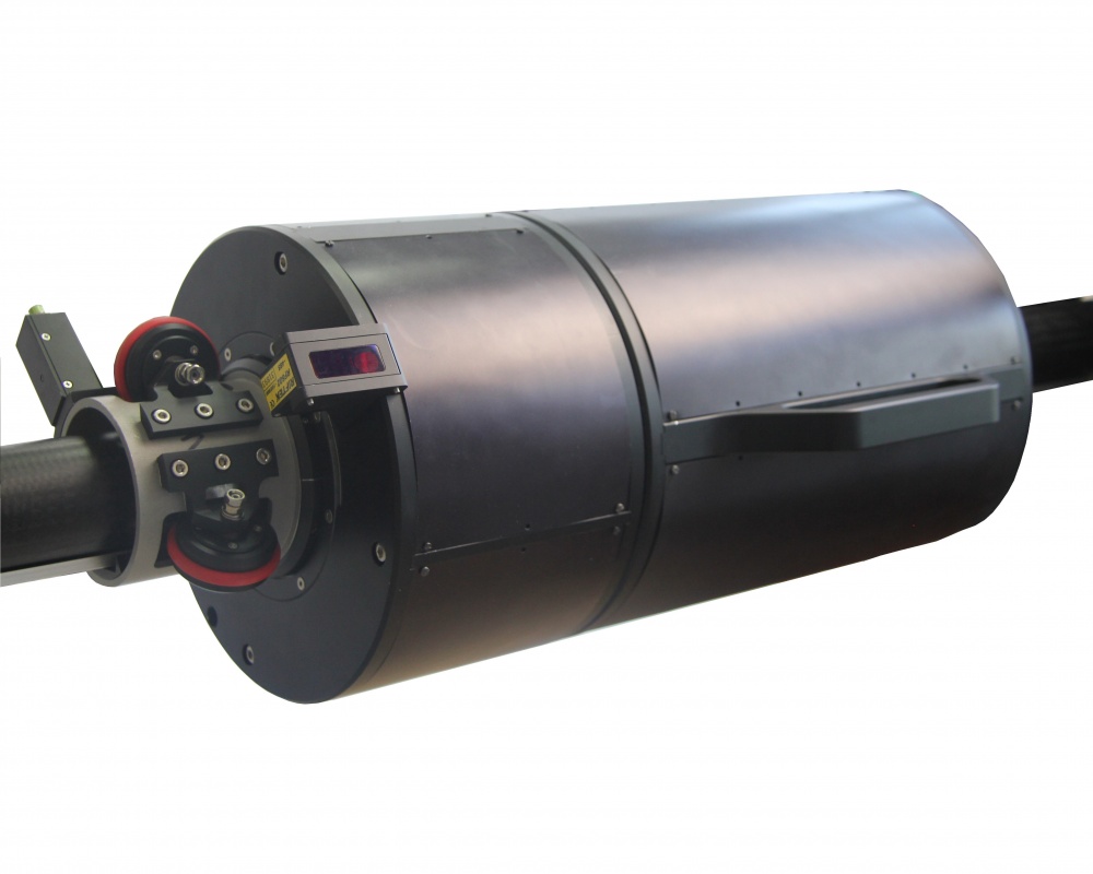
Laser scanning module
The main components of the laser scanning module and its overall dimensions are shown in the figures below.
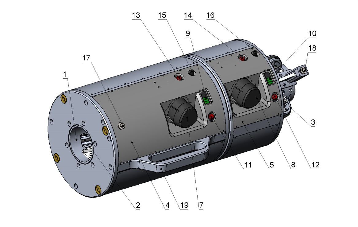
Designations:
1 - Sleeve. 2,3 - Wheel systems mounted on the sleeve (1). One of the wheels is equipped with an encoder (not shown) to control the linear position of the module.4 - Linear motion module.
5 - Rotation module.
6 - Laser sensor (installed on the rotation module).
7,8 - Batteries of modules 4 and 5, respectively.
9,10 - Battery charge indicators.
11,12 - Battery indicator control buttons.
13,14 - Power buttons.
15,16 - Wi-Fi antennas.
17,18 - End sensors.
19,20 - Carrying handles.

Installation frame
The main components of the installation frame are shown in the figure below
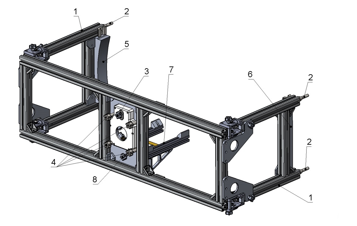
Designations:
1 - Folding legs. 2 - Screws for fastening to the end of the burner.3 - Screw for adjusting the upper part of the split prism for installing the guide.
4 - Four screws for fixing the scanning module.
5, 6 - Calibration blocks.
7 - Removable slipway.
8 - Slipway fixing screw.
Guide and centralizer
The guide is assembled from three elements. The centralizer is installed at the end of the guide.The assembly principle is illustrated in the figure:

RF096.Burner-IDmin/IDmax-L
| Symbol | Description |
| IDmin/IDmax | Measurement range (inner diameter), mm |
| L | Scanning depth, mm. |