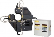
The system is designed for contactless scanning and geometrical parameters measurement of laminated tubes, made of PBL and ABL foil.
Application of the machine: large-scale production.
Laminated Tubes Geometry Measurement System RF092

Laminated Tubes Geometry Measurement System
| Name of parameter | Value |
| Measured diameters, mm | 13...50 |
| Diameter measurement accuracy, um | ± 10 |
| Foil thickness range, mm | 0,05…0,5 |
| Foil and weld thickness measurement accuracy, um | ± 5 |
| Tube length measurement accuracy, mm | ±0,1 |
| Interface to PC | Ethernet |
| Power supply | 220 V |
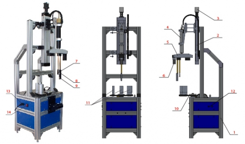
The system contains main frame 1 which carries linear translation stage 2 with stepper motor 3. Translation stage 2 carries rotation module 4 with in-built motor and encoder (not shown). Three-position linear translation module 5 with motor 6 is placed on rotational module The module 5 carries three triangulation laser sensors 7-9. Laser sensor 7 is intended for scanning of tube inner surface, laser sensors 8 and 9 are intended for scanning of tube outer surface. Measurement lines of sensors 7 and 8 are aligned. To eliminate the influence of the sensors on each other under the control of semi-transparent films, sensor 8 contains blue laser and sensor 7 — red one. The system contains rotational table 10, which carries three calibration cylinders 11 for automatic system calibration. Interface connector 12, power supply connector 13 and ON/OFF switch 14 are shown also.
The machine operates as follows:
The tube (not shown) is placed in measurement position under laser sensors by such a way that tube axis coincide with rotation axis of rotational module 4.
To get required accuracy measurement range of laser sensors must not exceed 5 mm, so all the range of tube diameters (20...50 mm) is divided on 3 subranges (20...30, 30...40 and 40...50 mm). Depending on tube diameter the module 5 places sensor into one of three possible control positions (there are three positions of sensors radial shift according to module 4 rotational axis).
The linear translation system 2 lets down laser sensors. During the translation sensor 9 determines the tube edge position (it is a start of tube length measurement) and then sensors 7, 8 determine the same edge.
After registration of tube upper edge the system translates sensors into position of tube shape control (10 mm from the edge).
Module 4 rotates module 5 with sensors. Sensors measure distances to tube inner and outer surfaces. The data are transmitted to PC where foil thickness, weld parameters and tube shape are calculated.
After completing a full revolution the system 2 lets down laser sensors and sensor 9 measures tube length.
Sensors are raised to upper position and measurement cycle repeats for the next tube.
Laminated Tubes Geometry Measurement System